Sunday, March 31, 2019

Basic Routing on Multilayer Switch - Connected Network - No VLAN

Today, we are going to try connectivity between two networks, connected by a multilayer switch.

Topology

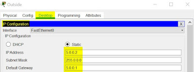
We see two networks 172.16.0.0 (inside) and 5.0.0.0 (outside). Inside laptop with 172.16.0.10 and Outside laptop with 5.0.0.10.  We check for ping between inside and outside laptops.

Task Breakup
  1. Configuring IP address on Laptops
  2. Configure IP address on Switch
  3. Analysis before routing
  4. Configure routing on switch
  5. Analysis after routing
1. Configuring IP address on Laptop

Click on Laptop -> Desktop -> IP Configuration
Inside - Laptop - IP Configuration
Outside - Laptop - IP Configuration
2. Configure IP addresses on Switch

As it is multilayer switch, we have to convert the interface into routing interface instead of switch interface.  'no switchport' is the command we use.  We set the interface according to the details mentioned in Topology.

routing#conf t
Enter configuration commands, one per line.  End with CNTL/Z.
routing(config)#int gig 1/0/1
routing(config-if)#no switchport 
%LINEPROTO-5-UPDOWN: Line protocol on Interface GigabitEthernet1/0/1, changed state to down

%LINEPROTO-5-UPDOWN: Line protocol on Interface GigabitEthernet1/0/1, changed state to up

routing(config-if)#ip address 172.16.0.1 255.255.0.0
routing(config-if)#no shut
routing(config-if)#exit
routing(config)#int gig 1/0/10
routing(config-if)#no switchport
%LINEPROTO-5-UPDOWN: Line protocol on Interface GigabitEthernet1/0/10, changed state to down

%LINEPROTO-5-UPDOWN: Line protocol on Interface GigabitEthernet1/0/10, changed state to up

routing(config-if)#ip address 5.0.0.1 255.0.0.0
routing(config-if)#no shut
routing(config-if)#exit

3. Analysis before Routing

Enable debugging at packet level

routing#debug ip packet 
Packet debugging is on
routing#

IP Routing information will be empty


routing#show ip route 
Default gateway is not set

Host               Gateway           Last Use    Total Uses  Interface
ICMP redirect cache is empty

Ping from Inside Laptop and Outside Laptop will not happen

4. Configuring routing on switch


routing#conf t
Enter configuration commands, one per line.  End with CNTL/Z.
routing(config)#ip routing
routing(config)#exit
routing#

Routing information will be populated with connected networks

routing#show ip route
Codes: C - connected, S - static, I - IGRP, R - RIP, M - mobile, B - BGP
       D - EIGRP, EX - EIGRP external, O - OSPF, IA - OSPF inter area
       N1 - OSPF NSSA external type 1, N2 - OSPF NSSA external type 2
       E1 - OSPF external type 1, E2 - OSPF external type 2, E - EGP
       i - IS-IS, L1 - IS-IS level-1, L2 - IS-IS level-2, ia - IS-IS inter area
       * - candidate default, U - per-user static route, o - ODR
       P - periodic downloaded static route

Gateway of last resort is not set

C    5.0.0.0/8 is directly connected, GigabitEthernet1/0/10
C    172.16.0.0/16 is directly connected, GigabitEthernet1/0/1

5. Analysis after Routing

Issue ping from Inside laptop(172.16.0.10) to outside laptop(5.0.0.2) .  It will be successful !!!


As packet debug is enabled, we will see the following dumps.


IP: tableid=0, s=172.16.0.10 (GigabitEthernet1/0/1), d=5.0.0.2 (GigabitEthernet1/0/10), routed via RIB

IP: s=172.16.0.10 (GigabitEthernet1/0/1), d=5.0.0.2 (GigabitEthernet1/0/10), g=5.0.0.2, len 128, forward

IP: tableid=0, s=5.0.0.2 (GigabitEthernet1/0/10), d=172.16.0.10 (GigabitEthernet1/0/1), routed via RIB

IP: s=5.0.0.2 (GigabitEthernet1/0/10), d=172.16.0.10 (GigabitEthernet1/0/1), g=172.16.0.10, len 128, forward

First 2 lines, indicates the routing process that happened for ICMP Echo Request packet with source IP(inside laptop) and destination IP (outside laptop)

Next 2 lines, indicates the routing process of ICMP Echo Reply packet with source IP (outside laptop) and destination IP(inside laptop)

Thursday, March 28, 2019

Simple VTP Operation

VLAN Trunk Protocol (VTP) in simple terms.  We configure VLAN information in one switch.  It will be passed on to number of switches connected to it.  Saving the effort of typing same VLAN information on all switches.
Topology
If help is needed on how to power on cisco switch in packet tracer. click here

Task Breakup
  1. Create Trunk between master and clients
  2. Create VLAN info in master switch
  3. Configure VTP server on master switch
  4. Configure VTP client on client switches
  5. Validation
1. Create Trunk between master and clients

Establish trunk link between 
  • Master(Gig 1/0/1) ------------- (Gig 1/0/1)Client1
  • Master(Gig 1/0/2) ------------- (Gig 1/0/1)Client2
master(config)#int gig 1/0/1
master(config-if)#switchport trunk encapsulation dot1q
master(config-if)#switchport mode trunk
master(config-if)#exit
master(config)#int gig 1/0/2
master(config-if)#switchport trunk encapsulation dot1q
master(config-if)#switchport mode trunk

client1(config)#int gig 1/0/1
client1(config-if)#switchport trunk encapsulation dot1q
client1(config-if)#switchport mode trunk

client2(config)#int gig 1/0/1
client2(config-if)#switchport trunk encapsulation dot1q
client2(config-if)#switchport mode trunk

2. Create VLAN info in master switch

We create few vlans in master switch.  Our intention is to pass those information to the client switches.  We assign an interface to vlan 300 (reason will be explained in step 5).  At this stage, observe that the vlan info in client1 and client2 is default.

master#conf t
Enter configuration commands, one per line.  End with CNTL/Z.
master(config)#vlan 200
master(config-vlan)#name vtp-200
master(config-vlan)#exit
master(config)#vlan 300
master(config-vlan)#name vtp-300
master(config-vlan)#exit
master(config)#vlan 400
master(config-vlan)#name vtp-400
master(config-vlan)#exit
master(config)#int gig
master(config)#int gigabitEthernet 1/0/24
master(config-if)#switchport access vlan 300
master(config-if)#exit
master(config)#^Z
master#
%SYS-5-CONFIG_I: Configured from console by console
show vlan br

VLAN Name                             Status    Ports
---- -------------------------------- --------- -------------------------------
1    default                          active    Gig1/0/1, Gig1/0/2, Gig1/0/3, Gig1/0/4
                                                Gig1/0/5, Gig1/0/6, Gig1/0/7, Gig1/0/8
                                                Gig1/0/9, Gig1/0/10, Gig1/0/11, Gig1/0/12
                                                Gig1/0/13, Gig1/0/14, Gig1/0/15, Gig1/0/16
                                                Gig1/0/17, Gig1/0/18, Gig1/0/19, Gig1/0/20
                                                Gig1/0/21, Gig1/0/22, Gig1/0/23, Gig1/1/1
                                                Gig1/1/2, Gig1/1/3, Gig1/1/4
200  vtp-200                          active    
300  vtp-300                          active    Gig1/0/24
400  vtp-400                          active    
1002 fddi-default                     active    
1003 token-ring-default               active    
1004 fddinet-default                  active    
1005 trnet-default                    active 

client1#show vlan br

VLAN Name                             Status    Ports
---- -------------------------------- --------- -------------------------------
1    default                          active    Gig1/0/1, Gig1/0/2, Gig1/0/3, Gig1/0/4
                                                Gig1/0/5, Gig1/0/6, Gig1/0/7, Gig1/0/8
                                                Gig1/0/9, Gig1/0/10, Gig1/0/11, Gig1/0/12
                                                Gig1/0/13, Gig1/0/14, Gig1/0/15, Gig1/0/16
                                                Gig1/0/17, Gig1/0/18, Gig1/0/19, Gig1/0/20
                                                Gig1/0/21, Gig1/0/22, Gig1/0/23, Gig1/0/24
                                                Gig1/1/1, Gig1/1/2, Gig1/1/3, Gig1/1/4
1002 fddi-default                     active    
1003 token-ring-default               active    
1004 fddinet-default                  active    
1005 trnet-default                    active  

client2#show vlan br

VLAN Name                             Status    Ports
---- -------------------------------- --------- -------------------------------
1    default                          active    Gig1/0/1, Gig1/0/2, Gig1/0/3, Gig1/0/4
                                                Gig1/0/5, Gig1/0/6, Gig1/0/7, Gig1/0/8
                                                Gig1/0/9, Gig1/0/10, Gig1/0/11, Gig1/0/12
                                                Gig1/0/13, Gig1/0/14, Gig1/0/15, Gig1/0/16
                                                Gig1/0/17, Gig1/0/18, Gig1/0/19, Gig1/0/20
                                                Gig1/0/21, Gig1/0/22, Gig1/0/23, Gig1/0/24
                                                Gig1/1/1, Gig1/1/2, Gig1/1/3, Gig1/1/4
1002 fddi-default                     active    
1003 token-ring-default               active    
1004 fddinet-default                  active    
1005 trnet-default                    active 

3. Configure master switch as VTP server

We create VTP. Usually contains following information.
  • Mode (server, client) - default will be server
  • Domain - it is case sensitive.  All switches with same domain name will have vlan configuration as in vtp server
  • Password - enhanced authentication
master(config)#vtp mode server
Device mode already VTP SERVER.
master(config)#vtp domain blogger
Changing VTP domain name from NULL to blogger
master(config)#vtp pass
master(config)#vtp password blog-pass
Setting device VLAN database password to blog-pass
master(config)#

master#show vtp status
VTP Version capable             : 1 to 2
VTP version running             : 2
VTP Domain Name                 : blogger
VTP Pruning Mode                : Disabled
VTP Traps Generation            : Disabled
Device ID                       : 0000.0CE1.E500
Configuration last modified by 0.0.0.0 at 3-1-93 00:47:49
Local updater ID is 0.0.0.0 (no valid interface found)

Feature VLAN : 
--------------
VTP Operating Mode                : Server
Maximum VLANs supported locally   : 1005
Number of existing VLANs          : 8
Configuration Revision            : 0
MD5 digest                        : 0x65 0xBC 0x5B 0x21 0xC3 0x28 0x52 0x80 
                                    0x9E 0xBA 0x83 0xA1 0x0E 0xF7 0x57 0xAD 

4. Configure client switches as VTP client 

We create VTP in the client switches.  Configuration will be the same as VTP master, except mode as client.

client1(config)#vtp mode client
Setting device to VTP CLIENT mode.
client1(config)#vtp domain blogger
Changing VTP domain name from NULL to blogger
client1(config)#vtp password blog-password
Setting device VLAN database password to blog-password
client1(config)#vtp password blog-pass
Setting device VLAN database password to blog-pass
client1#show vtp status
VTP Version capable             : 1 to 2
VTP version running             : 2
VTP Domain Name                 : blogger
VTP Pruning Mode                : Disabled
VTP Traps Generation            : Disabled
Device ID                       : 000A.F38B.B400
Configuration last modified by 0.0.0.0 at 3-1-93 00:47:49

Feature VLAN : 
--------------
VTP Operating Mode                : Client
Maximum VLANs supported locally   : 1005
Number of existing VLANs          : 8
Configuration Revision            : 0
MD5 digest                        : 0x65 0xBC 0x5B 0x21 0xC3 0x28 0x52 0x80 
                                    0x9E 0xBA 0x83 0xA1 0x0E 0xF7 0x57 0xAD 

client2(config)#vtp mode client
Setting device to VTP CLIENT mode.
client2(config)#vtp domain blogger
Changing VTP domain name from NULL to blogger
client2(config)#vtp password blog-pass
Setting device VLAN database password to blog-pass
client2(config)#exit
client2#show vtp status
VTP Version capable             : 1 to 2
VTP version running             : 2
VTP Domain Name                 : blogger
VTP Pruning Mode                : Disabled
VTP Traps Generation            : Disabled
Device ID                       : 0001.636E.B900
Configuration last modified by 0.0.0.0 at 3-1-93 00:47:49

Feature VLAN : 
--------------
VTP Operating Mode                : Client
Maximum VLANs supported locally   : 1005
Number of existing VLANs          : 8
Configuration Revision            : 0
MD5 digest                        : 0x65 0xBC 0x5B 0x21 0xC3 0x28 0x52 0x80 
                                    0x9E 0xBA 0x83 0xA1 0x0E 0xF7 0x57 0xAD 

5. Validation

After step 4, if we view vlan information in client1 and client2, all the vlan info that are configured in master switch will be present.  Note that we assigned gig 1/0/24 to vlan 300.  It will not be shown in client switches.  Port assignment is not part of VTP.

client1# show vlan br

VLAN Name                             Status    Ports
---- -------------------------------- --------- -------------------------------
1    default                          active    Gig1/0/2, Gig1/0/3, Gig1/0/4, Gig1/0/5
                                                Gig1/0/6, Gig1/0/7, Gig1/0/8, Gig1/0/9
                                                Gig1/0/10, Gig1/0/11, Gig1/0/12, Gig1/0/13
                                                Gig1/0/14, Gig1/0/15, Gig1/0/16, Gig1/0/17
                                                Gig1/0/18, Gig1/0/19, Gig1/0/20, Gig1/0/21
                                                Gig1/0/22, Gig1/0/23, Gig1/0/24, Gig1/1/1
                                                Gig1/1/2, Gig1/1/3, Gig1/1/4
200  vtp-200                          active    
300  vtp-300                          active    
400  vtp-400                          active    
1002 fddi-default                     active    
1003 token-ring-default               active    
1004 fddinet-default                  active    
1005 trnet-default                    active  

client2#show vlan br

VLAN Name                             Status    Ports
---- -------------------------------- --------- -------------------------------
1    default                          active    Gig1/0/2, Gig1/0/3, Gig1/0/4, Gig1/0/5
                                                Gig1/0/6, Gig1/0/7, Gig1/0/8, Gig1/0/9
                                                Gig1/0/10, Gig1/0/11, Gig1/0/12, Gig1/0/13
                                                Gig1/0/14, Gig1/0/15, Gig1/0/16, Gig1/0/17
                                                Gig1/0/18, Gig1/0/19, Gig1/0/20, Gig1/0/21
                                                Gig1/0/22, Gig1/0/23, Gig1/0/24, Gig1/1/1
                                                Gig1/1/2, Gig1/1/3, Gig1/1/4
200  vtp-200                          active    
300  vtp-300                          active    
400  vtp-400                          active    
1002 fddi-default                     active    
1003 token-ring-default               active    
1004 fddinet-default                  active    
1005 trnet-default                    active    

Sunday, March 24, 2019

InterVLAN Routing - Layer3 Switch

I try to do inter VLAN Routing without using Router.  Usually if layer 2 switches are used, we have to use a router to do inter VLAN Routing.  I use a standalone layer 3 switch to create VLAN and route packets between them.

Topology
There are 3 PCs in 3 different networks, and a layer3 switch.

Task Breakdown
  1. Configure IP Addresses in PCs
  2. Create VLANs in switch
  3. Configure Layer3 parameters in switch
  4. Validate configuration
1. Configure IP Addresses in PCs

PC Name IP Address Subnet Mask Default Gateway
PC-NET-1 172.1.0.100 255.255.0.0 172.1.0.1
PC-NET-2 172.2.0.100 255.255.0.0 172.2.0.1
PC-NET-3 172.3.0.100 255.255.0.0 172.3.0.1

Click on PC-> Desktop -> IP Configuration

Static IP Configuration in PC

2. Create VLANs in switch

Creating 3 VLANs 101, 102, 103 for PC-NET-1, PC-NET-2, PC-NET-3 respectively.

Switch#conf t
Enter configuration commands, one per line.  End with CNTL/Z.
Switch(config)#vlan 101
Switch(config-vlan)#exit
Switch(config)#vlan 102
Switch(config-vlan)#exit
Switch(config)#vlan 103
Switch(config-vlan)#exit
Switch(config)#

Assign the switch ports fa0/1(connected to PC-NET-1), fa0/2(connected to PC-NET-2) and fa0/3(connected to PC-NET-3) to VLAN 101, 102 and 103 respectively.

PC Name IP Address Subnet Mask Default Gateway Switchport interface VLAN ID
PC-NET-1 172.1.0.100 255.255.0.0 172.1.0.1 fa0/1 VLAN 101
PC-NET-2 172.2.0.100 255.255.0.0 172.2.0.1 fa0/2 VLAN 102
PC-NET-3 172.3.0.100 255.255.0.0 172.3.0.1 fa0/3 VLAN 103

Switch(config)#int fa0/1
Switch(config-if)#switchport mode access
Switch(config-if)#switchport access vlan 101
Switch(config-if)#exit
Switch(config)#int fa0/2
Switch(config-if)#switchport mode access
Switch(config-if)#switchport access vlan 102
Switch(config-if)#exit
Switch(config)#int fa0/3
Switch(config-if)#switchport mode access
Switch(config-if)#switchport access vlan 103
Switch(config-if)#exit

3. Configure Layer3 parameters in switch

Configure IP addresses to VLANs like the following.  IP addresses has to match the default gateway configured in the respective PCs

Switch(config)#int vlan 101
Switch(config-if)#ip address 172.1.0.1 255.255.0.0
Switch(config-if)#exit
Switch(config)#int vlan 102
Switch(config-if)#ip address 172.2.0.1 255.255.0.0
Switch(config-if)#exit
Switch(config)#int vlan 103
Switch(config-if)#ip address 172.3.0.1 255.255.0.0
Switch(config-if)#exit
Switch(config)#

To enable layer3 switch's capability to route packets, the following command has to be given

Switch#conf t
Enter configuration commands, one per line.  End with CNTL/Z.
Switch(config)#ip routing
Switch(config)#exit
Switch#

To view the routing table of the switch

Switch#show ip route 
Codes: C - connected, S - static, I - IGRP, R - RIP, M - mobile, B - BGP
       D - EIGRP, EX - EIGRP external, O - OSPF, IA - OSPF inter area
       N1 - OSPF NSSA external type 1, N2 - OSPF NSSA external type 2
       E1 - OSPF external type 1, E2 - OSPF external type 2, E - EGP
       i - IS-IS, L1 - IS-IS level-1, L2 - IS-IS level-2, ia - IS-IS inter area
       * - candidate default, U - per-user static route, o - ODR
       P - periodic downloaded static route

Gateway of last resort is not set

C    172.1.0.0/16 is directly connected, Vlan101
C    172.2.0.0/16 is directly connected, Vlan102
C    172.3.0.0/16 is directly connected, Vlan103

4. Validation 

Ping test has to be done from any PC to the other two PCs

Click on PC-NET-2 -> Desktop -> Command Prompt
Successful Ping from PC-NET-2

Basic VLAN Operation

I am performing a basic operation of VLAN using Packet Tracer.

Topology
It resembles a use case scenario, where 2 PC's from Marketing and Finance are placed in two different buildings.  Each building will have a 3560 multi-layer switch.  A connection is laid between switches.  We need connectivity between MKT-1 and MKT-2.  Also between FIN-1 and FIN-2.

Task Breakdown
  1. Setting Devices
  2. Creating VLANs in Switch
  3. Access Mode Configuration in Switch
  4. Trunk Mode Configuration in Switch
  5. Validating
1. Setting Devices
  • Configure IP Address in PC: Click on PC. Config -> FastEthernet0 -> Static -> 172.1.0.1
  • Set hostname in Switch
IP Configuration on PC

Switch#configure t
Enter configuration commands, one per line.  End with CNTL/Z.
Switch(config)#hostname BLD-1
BLD-1(config)#

Similarly configure IP Addresses and hostnames for all PCs and Switches as mentioned in Topology diagram above.

2. Creating VLANs in Switch

On both BLD-1 and BLD-2 switches create VLANs 2 and 3 for Marketing and Finance respectively.

BLD-1#conf t
Enter configuration commands, one per line.  End with CNTL/Z.
BLD-1(config)#vlan 2
BLD-1(config-vlan)#name MKT
BLD-1(config-vlan)#exit
BLD-1(config)#vlan 3
BLD-1(config-vlan)#name FIN
BLD-1(config-vlan)#exit
BLD-1(config)#exit


Observe that 2 VLANs are created waiting for the ports to be assigned.

BLD-1#show vlan
VLAN Name                             Status    Ports
---- -------------------------------- --------- -------------------------------
1    default                          active    Fa0/1, Fa0/2, Fa0/3, Fa0/4
                                                Fa0/5, Fa0/6, Fa0/7, Fa0/8
                                                Fa0/9, Fa0/10, Fa0/11, Fa0/12
                                                Fa0/13, Fa0/14, Fa0/15, Fa0/16
                                                Fa0/17, Fa0/18, Fa0/19, Fa0/20
                                                Fa0/21, Fa0/22, Fa0/23, Fa0/24
                                                Gig0/1, Gig0/2
2    MKT                              active    
3    FIN                              active    
1002 fddi-default                     active    
1003 token-ring-default               active    
1004 fddinet-default                  active    
1005 trnet-default                    active   

3. Access Mode Configuration in Switch
  • Fa0/1 of BLD-1 to VLAN 2(MKT)
  • Fa0/2 of BLD-1 to VLAN 3(FIN)
  • Fa0/1 of BLD-2 to VLAN 2(MKT)
  • Fa0/2 of BLD-2 to VLAN 3(FIN)
Now we have to assign ports of switches to VLANs 2 or 3 according to the PCs connected.  Here in our case:

BLD-1(config)#int fa0/1
BLD-1(config-if)#switchport access vlan 2
BLD-1(config-if)#switchport mode access
BLD-1(config-if)#exit
BLD-1(config)#int fa0/2
BLD-1(config-if)#switchport access vlan 3
BLD-1(config-if)#exit
BLD-1(config)#exit
Observe the Port assignments to VLAN

BLD-1# show vlan

VLAN Name                             Status    Ports
---- -------------------------------- --------- -------------------------------
1    default                          active    Fa0/3, Fa0/4, Fa0/5, Fa0/6
                                                Fa0/7, Fa0/8, Fa0/9, Fa0/10
                                                Fa0/11, Fa0/12, Fa0/13, Fa0/14
                                                Fa0/15, Fa0/16, Fa0/17, Fa0/18
                                                Fa0/19, Fa0/20, Fa0/21, Fa0/22
                                                Fa0/23, Fa0/24, Gig0/1, Gig0/2
2    MKT                              active    Fa0/1
3    FIN                              active    Fa0/2
1002 fddi-default                     active    
1003 token-ring-default               active    
1004 fddinet-default                  active    
1005 trnet-default                    active    

4. Trunk Mode Configuration in Switch

Interconnection of two Switches is through Gig0/1.  They have to pass traffic of VLANs 1 and 2 in it.  So, we make it Trunk mode with encapsulation IEEE Dot11q.

The configuration to be performed on both BLD-1 and BLD-2

BLD-1(config)#int gig0/1
BLD-1(config-if)#switchport trunk encapsulation dot1q
BLD-1(config-if)#switchport mode trunk
BLD-1(config-if)#exit
BLD-1(config)#exit

As Default VLAN 1 is already present in switch and we added VLAN 2 and 3, the resultant trunk port will pass all 3 VLANs traffic.

BLD-2#show int trunk
Port        Mode         Encapsulation  Status        Native vlan
Gig0/1      on           802.1q         trunking      1

Port        Vlans allowed on trunk
Gig0/1      1-1005

Port        Vlans allowed and active in management domain
Gig0/1      1,2,3

Port        Vlans in spanning tree forwarding state and not pruned
Gig0/1      1,2,3

5. Validating

To make sure our configuration works (without negative test cases involved), Following ping test should pass
  • MKT-1 (172.1.0.1) to MKT-2 (172.1.0.2)
  • FIN-1 (172.2.0.1) to FIN-2 (172.2.0.2)
Click FIN-1. Desktop -> Command Prompt